How to Build — DIY Air to Air Cross-Flow Heat Exchanger HRV
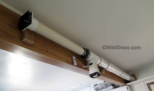
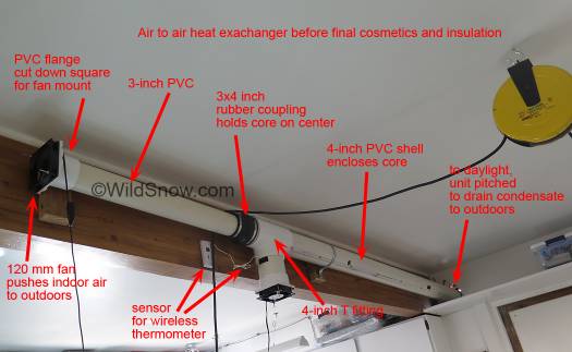
Completed heat exchanger located near ceiling in office workshop. Actual exchanger is covered with shiny bubble wrap insulation, white pipe stem protruding to left is the intake for indoor air, it is elongated to prevent short circuiting in/out vents. The two variable speed fans are the black objects located at the ends. Click all images to enlarge.
My studio-office-workshop where we deal with ski touring gear and more is remodeled to be fairly airtight. It needs ventilation. During summer here in our moderate climate I can simply crack a window and prop up a box fan if I need more than normal infiltration air flow. But paying to heat the planet’s atmosphere during our mountain winters is not in our business plan. Solution: air-to-air fresh air heat exchanger, also known as a heat-recovery ventilator or “HRV”. But do I want to sell my soul for an expensive commercial unit that I’ve heard tends to quit working after just a few years? Forget it. DIY to the rescue.
I came up with this DIY design by seat-of-pants based on years of experience with plumbing and ventilation parts, as well as being familiar with the basics of air-to-air heat exchange. It is simple. Easy to over-think. My design is intended to work and last for years, it is not a temporary science experiment.
The gist: Rig something that locates air flow from outdoors next to blowing air out from indoors — you swap the two flows — and let one airflow heat/cool the other so you “recover” energy. To do this you need an “element” or “core” that conducts heat well, a way to flow air next to the core, and a shell to contain it all. Variable speed fans, insulation and wireless thermometers round out the build of this HRV.
My design does all this quite simply. The core of this heat exchanger is 3-inch aluminum ribbed expandable “dryer” duct. Aluminum is highly heat conductive, thus a good material for heat exchanger core. Shell-enclosure is 4-inch thin wall CL200 white PVC plumbing pipe. (Note, commenters suggest that rigid aluminum duct pipe would perform as well as the expandable dryer duct, and be easier to work with. I agree. If you build, use rigid duct, perhaps with stick-on foam dots for clearance spacers.)
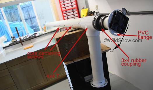
Testing a temporary lashup of the rig run through a window to cold exterior air here in Colorado, my design worked quite well from the start. It could probably be shorter. Having too much core surface area really doesn’t hurt anything, it just throws of your efficiency observations because the incoming air continues to be ‘tempered’ beyond an even exchange of energy. This can all be controlled with air speed as well as size, so don’t obsess on size. It’s easy to shorten the exchanger, harder to lengthen it.
The pipe spec is important. Regular schedule 40 PVC has walls too thick to allow sufficient air space around the aluminum duct core. “Drainage” or “sewer” pipe PVC is thin walled enough to create an air space, but doesn’t have the outside diameter of the common schedule 40 pipe, thus limiting your options for fittings. CL200 PVC pipe has the same outside diameter as schedule 40, but a thinner wall so the core has enough space around it for air flow. Perfect. (Other types of pipe could be better, but were time consuming to source in our mountain valley, see notes below).
The Build
The length I chose is somewhat arbitrary (8 foot shell). Testing shows this size to be totally adequate with my choice in fans (see parts list below), and could perhaps handle higher air volumes. You’ll need a place you can mount something of this length without messing up your interior decorating; a location with ambient temperatures similar to your living space. In a house, a crawl space or basement might work. Attic would be too hot in summer and too cold in winter. For residential use, creativity with location might be as important as the actual engineering as you need to consider things like distributing your nice fresh air. More, locating the vent that draws indoor air near the ceiling uses stratified warmer air which otherwise just stores unused energy. Here in my 25 x 20 foot single-room shop, I simply mounted up near the ceiling on the side of a wooden beam running down the center of the room. It works so it looks pretty. If it didn’t work I’d leave it there to humble me.
Bear in mind you’ll need to do an approximately 5-inch circular exterior wall penetration, check to be sure the required hole location doesn’t cut directly through a wall framing member and of course think about cosmetics and sun heating of your venting (more on that below.) Interior inlet and outlet are separated far enough to avoid short circuiting of the venting. Exterior vents should also be separated, doing so is not as critical as indoors as outdoors air is usually breezing around a bit.
Begin with an 8 foot chunk of the 4-inch PVC pipe, hopefully on a workbench rather than working on your knees.
1. Grab your 4-inch PVC pipe T fittings. Make end caps by inserting a 5-inch chunk of 4-inch PVC into one side of your 4-inch T fittings. Pound in the PVC pipe with a plastic or rubber hammer until the joint is snug. Don’t overdo it (you may need to reverse later), and don’t glue anything. More, take care not to blemish or otherwise damage anything, so you can return most of the parts to your big-box store if you don’t like the results. Your rubber 3×4 couplings will mount on the 5-inch pieces of 4-inch PVC, but don’t install the 3x4s couplings yet.
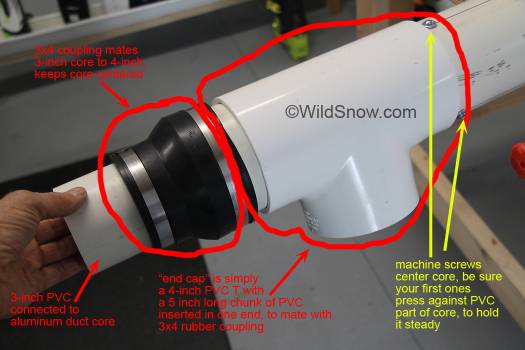
Your ‘end caps’ will end up looking like this. The 3×4 rubber flex coupling centers the 3-inch pipe core inside the 4-inch shell so air can flow around the core.
2. Stretch out your aluminum duct to about 7 feet. Attach a 3-foot chunk of 3-inch PVC to one end of the alu (this is your indoor side), and an 18-inch chunk of 3-inch to the other end of the alu. I made some connector sleeves out of aluminum dryer duct connectors, and taped the joints with duct tape. You won’t be able to access these joints for upkeep and if they fail the system won’t work, so consider cinching some wire ties over the duct tape or otherwise adding insurance.
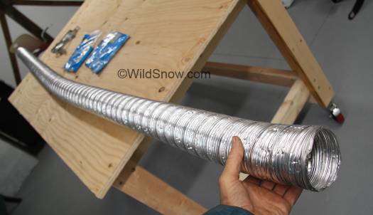
Stretching out the dryer duct vent used as core. Be careful not to crimp or compress, keep it nice and round.
3. Insert this resulting core assembly inside the 4-inch PVC shell.
4. Slip your end caps (from step 1) over the ends of the core and press fit the 4-inch T fittings to the ends of the 4-inch shell.
5. Spray some water on the protruding 3-inch pipe and slip the 3×4 rubber couplings to the point where they mate your the 3-inch PVC with the 4-inch.
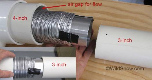
Core joints are made with some aluminum sheet and Gorilla Tape. Add plenty of tape for a good seal. I did not use silicon as I wanted things to be reversible if I disassemble to check for mold and seal issues.
6. Critical step: you need something to keep an airspace open between the core and shell. Some builds I’ve seen on Youtube and elsewhere use chunks of sticky foam and things like that to separate one surface from an other. I wanted something more stable and mechanical so I installed a few dozen machine screws in the PVC pipe shell at carefully figured depth to act as spacer for the core component. At each end of the shell, be sure three of these screws support the 3-inch PVC pipe. Thus, once the 3×4 fitting is tightened up the 3-inch PVC is supported and stable. See parts list for machine screw size I used, but due to exact choices in materials be sure to evaluate your own rig and choose the correct size screws. I placed washers under the screw heads to tune exact penetration depth.
Note that you’re using ‘machine screws’ because they have a flat end that won’t pierce the aluminum core if you’re careful about depth and turn the shell so you’re inserting the screws from the top, allowing the core to settle away from the screw as you insert. I took my prototype rig apart and inspected, the screws had caused no damage but I was quite careful while inserting.
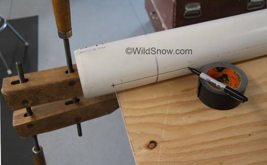
To place machine screws for centering core, draw a triad of straight lines on the shell, using workbench as a guide simply slide marker along on a spacer, in this case I set the marker on my roll of tape.
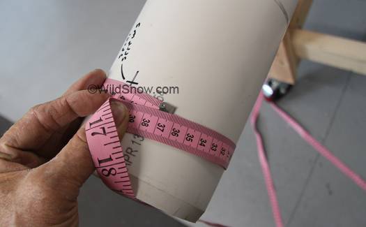
Measuring to space three lines of screws equidistante, so internal core is held nice and evenly away from shell, creating an air space for flow.
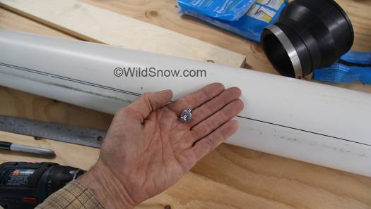
Machine screw with washers for precise insertion distance. It’s important these screws do not make holes in the core.
7. Now you should have a long chunk of 4-inch pipe with 3-inch stubs protruding from either end. The longer stub goes inside your living space, shorter to daylight.
8. Install your exchanger so the outdoor end (with shorter 3-inch pipe) goes to daylight. In my case, I cut a fairly neat hole in my exterior building siding, removed the T-fitting from the outdoor end of my exchanger, slid the 4-inch PVC through the hole, then replaced the T-fitting on the outside so it acted as a collar snugged up to the building siding, to help neaten the look of things. Slant the whole heat exchanger assembly at least 1/4 inch a foot to outdoors, so any condensate drains quickly to the outdoors. You’ll need some kind of support system indoors. I mounted on the side of a ceiling beam, which required simply using one pipe brackets and screws. You could hang from a floor joist in a crawl space with some plumbing strapping. Anything that works, just remember the whole thing needs to be pitched, and you need to think about how you’ll get both the ingress and egress venting into your living space with minimal pipe bends.
This is a good place to mention “short circuiting,” meaning the situation where your ingress vent air ends up being caught in your egress flow without mixing into your residential air volume. Indoors, prevent by putting some thought into locating your vents at least 3 feet apart. In my case, I wanted to utilize warmer stratified air up near my ceiling so I put my egress vent up high, and put my ingress vent lower.
9. Outdoor finish is easy.
A) Seal around the pipe where it comes through your wall, using something reversable in case you have to remove your rig for upkeep. If you anticipate much moisture, perhaps add a chunk of sheet metal flashing to act as a rain shield above your wall opening.
B) If you’ve not already done so, cut the end of the 3-inch pipe to make a slanted opening that faces downward. C) Cover 3-inch opening with insect screen. D) Place an approximately 24 inch stub of 4-inch PVC into the outdoors T fitting.
C) Add some sort of “bell” to the outdoor ingress vent. I used an expensive 4×6 PVC upsize coupling, something from the sheet metal venting world would be much cheaper and probably do fine. Idea here is to create a dust filter holder with lots of surface area. Cut out a circular peice of cheapo furnace filter and press-fit it into the 6-inch side of your “bell.”
D) Run a few sheet metal screws into your exterior pipe press-fit joints so they don’t work apart during expansion and contraction. Again, do not use glue, keep everything reversable and friendly to your air suppply.
10. Install fans indoors. Install a short length of 4-inch to exposed 4-inch side of the indoor T fitting, cut your 4-inch flange to fit a fan, and install the fan so it draws air into your living space. Likewise, install your 3-inch flange to the exposed 3-inch pipe protruding from the end of your assembly. This fan pulls air from indoors and blows it to the outdoors through your heat exchanger core. Use fairly small diameter machine screws to attach the 120 mm fans, and you can get diagonal holes in the PVC flanges to line up with those in the fans. I used small knurled nuts so I can remove and replace the fans with no tools.
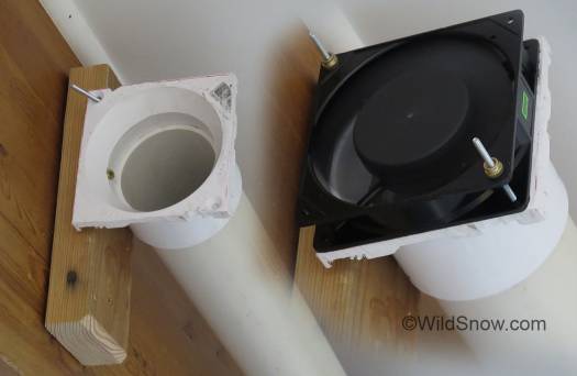
PVC ‘closet’ flange makes a perfect 4-inch fan mount. When sourcing, be sure flange mounts to pipe in such a way as to restrict airflow as little as possible possible. See parts list for suggestions.
11. Install two thermometer sensors in small holes you drill in the PVC pipe. One sensor outdoors in the end of the vent that provides indoor air (the one with the dust filter). This will be your “outdoor ingress” air temperature — generally the same temperature as your outdoor ambient temp, though located your heat exchanger outdoor components in a sunny area can cause temperature variations. Install sensor number two just behind your ingress air fan.
Speaking of outdoor vent locations, in my case I’m only running this heat exchanger when it’s cold outside, so I figured why not install where the outdoor vent gets cooked by the sun, for a tiny bit of added solar heating of my ingress air? Likewise, if you’re concerned about the sun messing with your heat exchanger performance, locate your outside venting in the shade.
12. It is important to insulate the do-it-yourself heat exchanger shell so you don’t get a false exchange when your input air sucks heat from your room’s ambient through the exchanger exterior pipe wall. In my opinion a thin layer of insulation is enough. I made a jacket out of that foil faced bubble wrap stuff from Lowe’s, seamed with duct tape. I like that stuff because it’s fire resistant (I think about fire safety with all my DIY projects since they’re usually so far outside the parameters of any building code standards.) For budget insulation, just wrap with bubble wrap. Note we use our regular plastic pipe for the exterior shell which slows down parasitic heat transfer. But you do need a layer of insulation, especially during extremely hot or cold outdoor temperatures. Since our exchanger is mostly for use during cold weather, I mounted it at ceiling height so any parasitic heat transfer is taken from warmer stratified room air, probably at nearly zero net monetary loss on the heating bill. If in doubt, just add another layer of insulation wrap.
13. Test. Fire up your fans when your indoor and outdoor temperatures are significantly different. Watch your readings on your thermometers. Hopefully you’ll be surprised how good this works. I was.
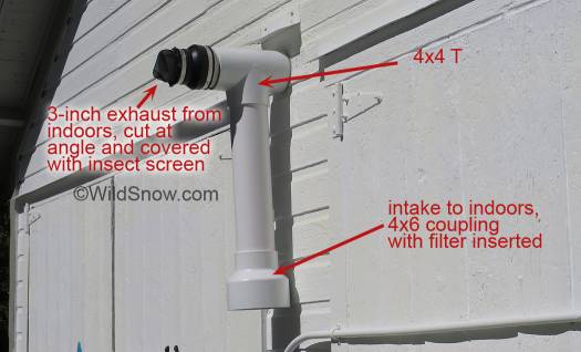
Outdoor venting, on the sunny side of my studio-shop-office. Sun heat in winter adds to efficiency and prevents mold. Vent from indoor to out is screened (upper) to keep out insects or small human beings, input to indoors is filtered with a furnace filter in the “bell” made from plumbing fitting. This odd looking configuration is due to the intake and exit needing to be separated to prevent short circuiting and mixing of input and output air. Unfortunately this configuration on the street facing side of my shop, but needs to be on the sunny side for added efficiency and mitigation of any condensation problems. To pretty it up I’ll probably build a wood valance over the whole thing, so it looks less like I’m doing what we politely call “Colorado indoor gardening.”
PARTS LIST
Thermometer, multiple sensor from Amazon, one. $56.00
3″ x 8-0 Semi-Rigid Flexible Aluminum Duct, Product #L301 from Lowe’s (used for core that’s key to making this project function), $10, one.
4″ A-2000 PVC (thinner wall than schedule 40), 12 feet, $22.00 (from plumbing supply house).
3″ A-2000 PVC (thinner wall than schedule 40), 6 feet, $10.00 (from plumbing supply house).
4″ schedule 40 PVC T fittings, 2, couldn’t find at Lowe’s, $11 each from plumbing supply house.
6″ x 4″ Sch 40 Reducing Coupling (used for filter at outdoors input end of unit) $11.00
(It is important that the two flanges below, used for mounting fans, fit OVER your pipe so you don’t get an airflow restriction from the thickness of an interior coupling. All fitups in this project are friction fit, no glue is used, so if a fitting needs to be stabilized run in a sheet metal screw through a pilot hole. Leave most fittings as friction fit so you can easily take the exchanger apart for later cleaning, upkeep, or modifications.)
PVC flange (toilet connector, closet flange) for mounting OVER 3-inch pipe for mounting fan on 3″ PVC, Lowe’s item 253221, $4.00, one
PVC flange as above, for mounting OVER 4-inch pipe, Lowe’s item 253231, $5.00, one
(These rubber connectors work very nicely, but are a bit pricy but necessary for easy assembly of the project.)
Rubber “no hub” 4-in x 3-in Dia Flexible PVC Coupling Fittings with hose clamps, Lowe’s item 23478, $9.30 each, twoSmall chunk of furnace filter element, cut circle to press fit into outdoors end of unit.
This is the Cooltron fan model I ended up using, claimed 56 CFM at max speed.
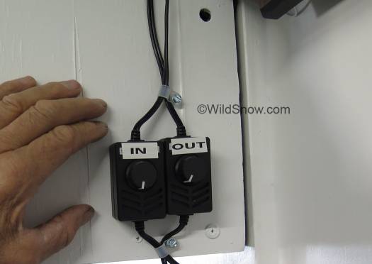
And this is the fan speed control.
Drill bit for installing core centering screws, 9/64 allows self tapping of machine screws used as centering supports for core. Do not use sharp ended screws at they’ll penetrate the core.
3/4 inch 10/24 Phillips head machine screws <> 20 3/16 inch flat washers to prevent machine screws from protruding too far inside, use two per screw. <> 40
Mold warning: Any air-to-air heat exchanger introduces the possibility of mold growing in your ducts, whichever part produces condensation (in our case, the duct moving air from indoors to outdoors is where condensate may occur.) While we have little worry about this, since the air in the our heat exchanger exhaust space is blowing to the outdoors, preventing mold is always a good idea. Testing will reveal the reality of this, but at the least we’re thinking that simply keeping a spray bottle of humidifier mold preventative and spritzing some of this into the fans now and then will take care of the problem, as well as letting the sun bake our exterior venting. Speaking of contamination, don’t forget to eventually install a fabric type filter on the input (to indoors) end of your venting, as well as placing screen wire over the other outdoor vent (outdoor air to indoors). Luckily our design begins with a nice larger 4-inch input; I stepped this up to a 6-inch diameter fitting that holds a circular chunk of furnace filter.
http://www.engineeringtoolbox.com/ventilation-heat-recovery-d_244.html
AC Infinity AI-120SCX Speed Control Fan Kit for Cabinet Cooling, Single 120mm
NOTES
The way I understand it an exchanger that’s efficient will result in input air being close to room temperature. Apparently, this is easy to accomplish with cold outside air and warm, humidified indoors air, if you slow down your air movement enough to allow a leisurely exchange of heat-energy between the two air volumes.
In real-world use, you want your heat exchanger to be somewhat efficient, but spending a fortune and taking up space for something super efficient may not be practical. Perhaps the best rule of thumb is so long as your air coming in from outdoors is fairly close in temperature to your indoor ambient you’re doing fine. If the difference becomes too great, either the exterior-interior temperature differential is extreme, or you need to slow down your fans, or build an exchanger with more core surface area (or both). Also, as the the difference in outside and indoors temperatures increases, your performance may degrade. My rig works incredibly well at differentials of around 30 degrees F, but I’m certain I’ll see a fall-off in performance when it’s 10 degrees outdoors and 68 indoors.
In the case of this project, testing revealed astounding efficiency with indoor temperature around 67 degrees and outdoor around 38 degrees. Incoming air was 66.4 degrees with the shell well insulated to prevent parasitic heating of the shell from ambient indoor air. Turned out my first choice of 45 CFM fans was a bit too limited at times for the ventilation I needed while overcoming airflow friction resistance, so my final build uses variable speed fans with that claim to do 56 CFM (links for those below). I don’t usually run the fans at max speed and they seem to move enough air, so perhaps in the end I could have used the 45 CFM fans. Whatever, not a big deal to experiment with different fans (mine are attached to the unit with thumb screws, so I can swap in minutes).
I also paid close attention to performance during cold Colorado winter mornings, sometimes around zero farenheit. Performance was fine.
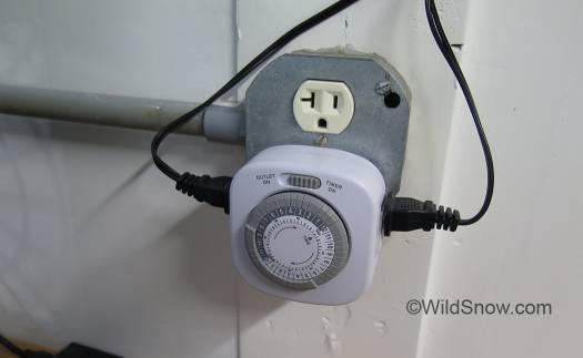
IMPORTANT: Locate your fan controls for easy access. Remember you are the brains of this rig, not a microprocessor like those of the commercial heat exchangers. For example, say you’ve had your heat turned off all night, it’s now chilly in your living space, and it happens to be warmer outside at your ingress air vent due to it being a sunny morning? Just turn off your egress fan (the one pushing air out of your living space) and turn your ingress fan up full bore to suck that free heating indoors. Also, rather than running this thing 24/7, consider hooking your fans to a timer that turns your exchanger totally off during the coldest (or hottest) part of the day. For example, I’ve set mine to shut down around 11:00 pm and wake up in the morning an hour or so before I usually sit down at my desk.
One might ask “can an engineer figure all this heat recovery ventilator stuff out with math so I’d know what length, what CFM fans, that sort of stuff?” Perhaps with sophisticated computer modeling and field measurements this could be done. But in a practical sense, no. The engineer would have to know exact CFM of air movement inside the ducts, along with exact surface area of your core. Even then, they would have no exact way to account for turbulence in the air flow. Parasitic cooling or heating of the unit by indoor air would also be difficult to calculate. Probably a better way to refine these units is simply to crowd source the experiments.
One measurement you’ll probably want is the CFM you get when everything is running and your temperatures look good. Roughly measuring CFM can be done by placing a plastic garbage bag of known volume over your indoors inlet, counting how many seconds it takes to fill, then doing the math.
I’d imagine a person with sufficient time could source my fresh air heat exchanger design using all “drainage/sewer” PVC known as thin wall DWV. Doing so would be excellent. Crux is acquiring fittings such as the fan mount flanges. Next build I do I’m giving DWV a try — doing so would probably save at least $50 over the build I did using local over-the-counter materials. See http://www.pvcfittingsonline.com/fittings/dwv.html
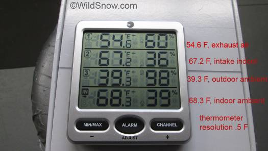
Multi-sensor indoor-outdoor thermometer is also essential, otherwise you’ll just be guessing at performance.
Comments
33 Responses to “How to Build — DIY Air to Air Cross-Flow Heat Exchanger HRV”


I have considered building a similar system in a new small house in northeast Tennessee. We have 20 foot lengths of aluminum irrigation pipe leftover from farming and I imagined constructing a shell and tube system with fans. Some pipes are 5 inch and some smaller. I wonder how necessary it is to create the turbulence for mixing the air since my tubes would be much longer? Also, would you think the direction of the air would be more efficient if running the same direction or opposite directions?
Congrats on ingenuity and thanks for posting your invention.
Great work Lou!
Thanks for the insight. Well done.
If you wouldn’t mind reflecting on my thought to bring in fresh air for a kitchen exhaust hood. commercial size. 1200 cfm.
Allowable with out make up air in my neck of the woods isjust under 400 CFM. I am looking at a minimum make up air of 2 – 6″ ducts with barometric dampers.
I am considering 1″ insulated duct board. construct 8″ x 24″x 16′ long trunk. suspend the expandable round duct inside. Install barometric dampers at the end of the 16′ run at the inside of the home. Now I will need to introduce warm house air into the insulated trunk line at the barometric damper end and let it discharge back in the house space at the end closest to the exterior.
I am considering a Panasonic 110 – 150 cfm adjustable bath fan mounted in another portion of the basement duct ed to the trunk to warm the make up air. we are in Erie pa and condensation in the winter could be problematic. So I felt a heat exchange may temper the air before I let it loose in the house.
common place is to run the duct to the return air of the furnace, mounting the damper there.
condensation in the 6″ round and the insulated duct is still a concern that could be drained to a sump crock.
Also the amount of air and the length of trunk may not be enough to take the chill off in February
respectfully skip
Skip, I did a super low end version of air tempering years ago, by simply installing long runs of sheet metal ducting through our crawl space, from daylight to our return-combustion air for the water heater and gas fireplace. Very cost effective, passive with no fans.
As for your idea, so long as you can run inlet air next to outlet air the concept is good. Noise of the fans is an issue, also, the crawl space ambient temps need to be different enough from outdoor air to instigate heat exchange.
Condensate with these systems is a big issue. Watch out what you get into. The cost and worry of condensate and mold might make it better to just crack a window and spend a bit more on heating.
My advantage with system in blog post above is it’s not a “living” space with cooking etc. moisture (it’s my office workshop), and we live in a super low humidity climate. After a winter of testing I’m not having any trouble. It’s been turned off all summer.
‘best, Lou
Very cool. It probably wouldn’t be worth the added expense/complexity, but using a bunch of small diameter tubes and couple of manifolds instead of dryer duct might make for greater surface area/heat exchange (and maybe drain better).
See, interesting idea on the tubes. Problem is keeping it simple. My design is based on DIY shower grey water heat exchangers you can find on the web, using similar plumbing parts and concept. It’s amazingly simple how the rubber connectors center the core as well as sealing the ends of the shell. The most complicated part for me was the detail work, choosing and mounting the fans, daylighting to exterior, insulation, bracketry, etc.
The thing really works, my shop/office has incredibly invigorating fresh air and the incoming air temps are impressive.
You can easily make one of these that will heat up your incoming air to 100% ambient, but then you’re not getting a beneficial heat exchange after a certain point, just moving too much air. The concept is about balance. You want to “recover” just enough heat from the outgoing air as to utilize some of what would otherwise be wasted with normal room ventilation (e.g., cracked window, convection air circulation).
What’s crazy is science geek stuff also says that if water is condensing on the way out it’s actually releasing latent heat that can bump up the performance of the exchanger beyond what you’d expect. With the added problem, of course, with dealing with the condensate.
My dryer duct core with outgoing air would indeed be difficult to clean as it’s ribbed and fragile. Though it’s cheap and easy to replace. Thing is, I’ll bet this same rig made with a smooth bore aluminum pipe would work quite well and be very easy to clean. And like I said in article, spritz with mold preventative now and then, in the exit air stream, problem solved. (Of course, mold in the exit air stream is not as big a deal is mold in the incoming air stream, which isn’t going to happen if this devices is only used in a heating situation. (If a similar rig was used to cool warm air coming in from outside, then there would be a ton of condensate in the incomming duct, which could be a difficult problem.)
At Speedymetals.com, for example, you can get 3″ o.d. x .065 wall aluminum tube made of 6061, which would be really nice stuff for this sort of project. A 72 inch stick is only $30 USD! Indeed, if I build another exchanger I might try it with the alu tube instead of the dryer duct.
I’m trying to get around to making the similar heat exchanger for shower water, using a copper plumbing pipe core carrying pressurized cold water in, and the shell moving grey water out, but the benefits are not as tangible and the crawl space work is a pain.
‘best, Lou
I haven’t really thought it through (much less actually tried to make it) but I suspect you could use the same rubber connectors and make the manifolds by drilling some holes in a plastic disk cemented inside a section of the same PVC used for the duct end fittings. Of course, your system apparently works great as it is, so no need. I just can’t resist the temptation to ponder mods. I hope you get around to the shower project. It sounds really interesting.
(Re. greywater: I’ll spare you a description of the solar and gravity powered system I’ve been using to try and maintain a (tiny) lawn here in California…)
Greywater is the gorilla in the room. More difficult to deal with than most people realize. At the least, a very inexpensive heat exchanger on a shower drain line probably pays for itself pretty quickly, assuming no cash labor costs were involved.
I’m gather from Google that this concept in general is called a “side arm” heat exchanger, due to the two “arms” for inlet and outlet of the shell-case.
This is my favorite DIY of a shower exchanger. It’s probably what I’ll build.
https://www.youtube.com/watch?v=mEExlOX458Y
I wonder if exhausting warm air through the outer pipe (reverse of your system) would allow better (easier) draining of condensation? Airflow and gravity would carry it out the exit pipe. Heat transfer to the aluminum duct should be the same. Also less need to insulate the first portion of outer duct..
Looks like a clever design. One thing, though… it looks like you have your warm air leaving through the inside aluminum dryer vent, and the cold air coming in through the PVC. Therefore, the condensation will be both inside the dryer vent, where it can’t drain well, and outside of the PVC, where it drips. Wouldn’t it make the condensation easier to deal with if the cold air came in through the center dryer vent, and the warm exhaust in the PVC? That way the condensation would be only on the outside surface of the aluminum dryer vent, and contained in the PVC pipe where it is easy to drain cleanly. And the system would be much easier to clean if need be. Be sure to filter the airstreams to prevent lint from clogging the system, stealing your efficiency, and getting moldy.
One more thought…. during the heating season, run it during the warm part of the day, and during the cooling season, unless you leave your windows open, we still need ventilation, run it during the coolest part of the night.
And, instead of the bolts through the side as spacers, how about buying a couple of extra PVC couplers, cut the big pipe into 3 ft sections, and PVC-cement a couple of small PVC rods in the bottom, glueing just at the ends. No leaking bolt holes, no vibration wearing of the dryer vent, and full support along the whole length.
FWIW
Bill, thanks for visiting this somewhat buried page. A bit off-topic but then, it relates to tuning a dwelling in winter climate, in a zone where people ski…
Yes, the air out-in ducting could go either way (with thought to how the input-output openings are located). I opted to blow the dwelling air out through the aluminum core. With higher humidity dwelling air and cold outdoor air, there could indeed be quite a bit of condensation inside the dryer duct core. In my case, that’s not happening so it’s working fine as is.
If the dwelling air was blowing out via the channel surrounding the aluminum core, then yes, the insulation around the shell would probably not be necessary in most situations.
The system is pitched to the building exterior and set up so condensate will drain quickly. Even so, condensate is a concern with any air heat exchanger, commercial or owner-built.
Indeed, if someone is building this type of system for use in a higher condensation situation, it would perhaps be good to blow the dwelling air out through the channel on the outside of the aluminum core, so the condensation could more easily drip down to the smooth PVC pipe and run to the outside. Either way, you’re going to get moisture on the surface of the aluminum, which could cause problems with mold and such, as can happen with any cross-flow fresh air heat exchanger.
Saving grace is that the moist surfaces (in cold climate) are exposed to air blowing _out_ of the building, thus if mold develops it’s less risky.
The aluminum is somewhat anti-mold and anti-bacterial, but it it gets coated with dust then all bets are off.
Your suggestion to filter _all_ air is excellent and should indeed be mandatory. I’ll mod the exchanger this summer to make that happen.
Plan is to uninstall system this summer and inspect interior for condensation issues.
In my opinion, mandatory upkeep is to mist humidifier anti-mold-anti-bacterial treatment into both the input and output every few weeks.
The machine bolts as spacers do not leak at all, and they don’t make holes in the aluminum if installed with care. Nonetheless, as you suggest there could be a better way. Simple stick-on foam pads on the aluminum core could still be viable and would enable pulling out the core for upkeep and inspection without removing all the machine screws. It might also be better to use smooth rigid aluminum sheet metal duct rather than the dryer duct. Regular smooth duct would be much more durable and easier to handle (but it’s more expensive). Without the ribs of the dryer duct, rigid smooth duct would perhaps not be as efficient in the heat exchange, but that might not matter as we’re talking a lot of surface area in this 8-foot long design, and it can be made longer, though at some point the fans and airflow will get noisy.
The dryer duct ribs probably do trap condensate moisture in their creases, that alone might be a reason to change design to using rigid alu duct for the core.
Lou
Bill, yes, I only use this during cold season and the timer indeed turns it off at night and on during the warm part of the day. That’s huge in terms of efficiency. I’m not in the studio at night anyway, so might as well pretty much shut the place down. Meaning I need a better heater thermostat as well (never ends). Lou
Dear Lou,
I was at a Habitat for Humanity Restore today and saw an air exchanger for sale which prompted me to see what I could build from scratch. I googled the subject and found your blog. I need an air exchanger for my shop to improve the air quality and remove dust. I was glad you mentioned the problem that would occur if dust gets into the system. I might have to do even more filtering for it to work. It might also mandate that I use smooth aluminum pipe so I can take it apart more often for cleaning. At any rate, thanks for the article. You are very articulate and your photos are great and easy to understand. If I do actually build one, I will send pics once I have proved it out.
Hi Al, cool you found my post! The exchanger is working super well, it’s not high volume, I put a large bell filter on end that pulls air from outdoors, could do that on the end that draws air from indoors, but have not found it necessary. An aluminum interior pipe would be better than the dryer duct, easier to handle and I’m sure just about the same efficiency, though the dryer duct is amazing, huge amount of surface area and the ribs add turbulence to the flow. Let me know how it goes. Lou
Lou,
Been considering such a system for whole house HRV and fresh air up in Idaho. I plan to parallel multiple configurations to achieve 0.5 ACH. My engineering computations say it should be easily doable, and the computer case fans are so cheap it should pay for itself before a single season is up.
One thing you mentioned was that the air flow coming into your shop was measured at only 4.3 CFM, and with two 69 CFM fans driving it. The friction losses in your straight shot from inside to outside are very low, and you should get the CFM performance for the exhaust fan out of the shop that the fan manufacturer specifies. To be honest, I would think that you would get closer to 43 CFM into the shop with the intake fan completely off, just using the exhaust fan and the negative pressure it produces.
I am thinking either you had a typo, maybe misplacing the decimal point, or a measurement mistake on the CFM you reported as input, or else you wouldn’t be as comfortable as you are. A 16 hour exchange also equates to an 0.0625 ACH, which is less than what window and door opening leaks generally produce. Just using the exhaust fan, you ought to be close to one air change per hour.
My gut feel is that you actually have a much more nicely balanced system than you suggested.
i would be interested if you have done any more measurements on your intake CFM.
Mark Powell
Mark, I’ve got speed controls on both fans, it was a while ago but I recall the measurement I did was with the controls where I like them for noise etc., and I used the inflation time of a garbage bag to measure CFM, but yeah, could be a typo as well! I think you are correct in that if the fans are running at their normal speed the flow is pretty good. I turn the fans up when I’m using my studio as a workshop, but normally I’m just sitting at desk, with no cooking or anything else, so the air exchange rate can be pretty low. Let us know how it goes, I think this type of system works well so long as the climate is fairly dry and any condensate is in the outflow, which should be pitched so it drains, and inspected occasionally for mold just to be extra safe. Lou
P.S., someone mentioned using rigid aluminum vent pipe for the core instead of the meager and flexible dryer duct, if I had it to do again I’m probably try the rigid vent, perhaps a bit longer overall. I’ll take system apart this summer and inspect, and report back here. Lou
Mark, you are probably right on CFM just using one fan, but are you concerned about causing a negative pressure in the building, causing infiltration around all the doors and windows?
I’m wondering if the fan blades were designed for full speed, and they just can’t generate the static at low RPM. I wonder about using a different fan design tat would work slowed down, but control one to keep the pressure at about zero. In commercial buildings, they keep pressures about plus 0.05 inches WC.
Bill,
In Lou’s original description, he said, “With my inlet fan turned up to max I get about 4.3 CFM, which in my shop space results in a complete air exchange every 16 hours, which is fine and tests well in real life by paying attention to how quickly odors are removed from the room.”
He said he was using 69 CFM fans, so if his exhaust fan (pushing straight line out, virtually no friction) was running at this speed, he had about a 64.7 CFM deficit. That kind of negative pressure would suck outside air in everywhere it could, especially around doors and windows. He would not be as comfortable as he indicated sucking in so much cold air, so I think he just measured his intake air flow funky or something.
If you look at his pix with the temps and humidities, Lou’s exhaust air did not get that cold. He had a ton of margin to work with. A perfectly balanced system (more work than necessary, cutting down the tubes to shorter lengths) would have the exhaust air and ambient outside air temps much closer, within a degree like the difference between his inside ambient and incoming tempered air.
Lou,
The rigid aluminum duct is just about as cheap as the dryer vent hose, and any heat transference differences between them won’t be measurable. You have so much surface area and the thin walled aluminum has such a high heat conductance, it will work just as good. Plus, with the rigid duct, won’t need the spacer screws.
I will be using the rigid Al duct to carry the outside air in, and the PVC around it for the inside air to go out. The inside air has the condensable humidity, not the outside air, so all the condensate should be inside the PVC. As you mentioned, sloping this configuration should blow the condensate out outdoors. Have to watch for freeze up though when it gets down to -30.
You have had a couple of winters with this system now. How did it perform when it was say 10 F outside?
Mark Powell.
Just a quick order of magnitude sanity check on the air volumes – maybe Lou remembers how it went – 4.3 cubic feet is about 32 gallons, so 4.3 CFM would fill a 30 or 36 gallon garbage bag in about a minute. That is not a lot of air.
A couple of random thoughts…
If frost is an issue as it will be on a cold day here in Minnesota, the simple way to deal with it is to duty cycle the unit, maybe 30 minutes on and 30 minutes off. Give the frost a way to just slowly melt. There are devices called “repeat cycle timers” that could be built into the electrical outlet box. The ones that I am thinking of are built into about a 2″ x 2″ x 1/2″ square plastic potting box with a mounting hole in the middle, and have 1/4″ spade lugs. The timing values are set up with resistors. I’m guessing that someone can find a surplus timer for a couple of bucks.
Commercial HRVs that use a corrugated plastic diamond shaped heat exchanger have more trouble with frost, because the passageways for the air are so small, so they have to pay more attention to defrosting. They use a damper to divert the exhaust air back to the room, stop the outside air fan, and just run the exhaust fan in this bypass mode for a few minutes. That complicates the design, though.
Lou, you briefly mentioned humidity. It is probably not an issue for you unless you are either humidifying in the winter or mechanical cooling in the summer (which spends a great deal of its energy wringing out moisture). In commercial units where humidity is a concern, they use corrugated paper heat exchangers. You could do the same thing by making the inner tube out of paper. Some of the high humidity in the summer outside air would migrate through the paper into the exhaust stream, saving your AC unit the job of removing that moisture. Frost in the winter might be a big problem with this method, though.
It would be an interesting experiment to run two units side by side, one made with straight aluminum stovepipe, and the other with aluminum dryer vent to see if the surface roughness and additional surface area of the dryer vent made a difference.
Bill
Thanks for all the attention to this project guys, I probably messed up on how I measured air flow. More, it appears the specifications on the fans I used were changed in the Amazon description. I’ll try to keep everything consistent in my blog post as well as comments. The fans I used are 20 to 56 CFM variable speed fans (according to specifications), and when set to slightly below max speed, they move what I feel is plenty of air though it’s indeed not a huge gust. Bear in mind I’m using this machine in a ~500sf one-person office/studio/workshop with no kitchen, no bathroom, no sleeping, so I don’t have a need for large amounts of fresh air. The design could indeed be enlarged, or doubled, for more flow. Larger fans could help move more air without too much noise.
While my writing studio is also a workshop, I do dust generating projects outside, so I don’t need air flow for dust control. I do run a stand-alone air filtration unit now and then, for example while sweeping, or when my allergies are acting up.
The idea behind two fans is twofold, 1)they force air flow through the exchanger in the event the dwelling is not perfectly sealed, which is good, for example after a few years the weather seal at the bottom of my exterior door is shot, cheap Lowes windows are not perfect, etc. 2) I don’t feel these types of fans do well in overcoming duct friction, so two of them instead of one for that as well.
After pondering the issue of core materials, I totally agree that rigid aluminum duct would work fine, and make this design easier to construct.
Regarding the issue of bringing exterior air in through the shell or the core, I remember having some good reasons to bring the air in through the shell, and insulating the exterior of the shell, but for the life of me I can’t remember the reasons (smile). I can see the logic of bringing outside air in through the core, if I built another exchanger I’d probably try that. As it is, my configuration works so I’ll not take time remodeling.
To answer another question above, during the first winter of operation I payed close attention to performance during cold temps, sometimes around zero fahrenheit. Worked fine. If the thermometers had indicated any problem with cold air overcoming ability of exchanger to do its thing, I could have tuned the performance by changing the speed of the fans.
Regarding humidity, simply not a problem due to our climate as well as what this dwelling space is used for (as I allude to above).
To avoid confusion, I’ll edit my statements about how much air volume I’m getting. Indeed, it appears I created some confusion in my writing, as I FIRST used 45 CFM fans, then changed to final build using 20 to 56 CFM variable speed fans (approximately, anyway). If the fans I used did indeed result in too little CFM, one could always use better/larger fans provided the exchanger had enough surface area. I like a quiet office when the music is turned off, so I was conservative with my choice in fans.
It’s possible I made the unit too long, which would result in more air friction without any improvement in heat exchange performance. If I had more time it would indeed be fun to make a shorter unit and run it as well.
Followed your exact build to the letter. Doesn’t work. Air coming in is still cold. That is with no inlet fan running, just natural suction when exhaust fan is running. I think the 3″ aluminium flex duct is too thick and choking off the exhaust port. Maybe i’ll try using a 2″ round aluminium down spout for my core instead of dryer duct. Would love to know where I went wrong. How much heat transfer should I expect with this set up anyway? If its 80 degrees going out, and its 50 outside, what. Should i realistically expect to come in, 70, 75 ?
Hi Dave, sorry to hear that. Honestly, mine works according to the temperature probes . I’m traveling at the moment but am happy to explore more with you in a few days. I can say that having two fans, with independent variable controls, enables one to tune the thing. The key, if the air coming in is cold, is it warmer than outside? If so, the machine is working to some extent and providing tempered fresh air, much better than opening a window…
One other thing. Are you expecting the incoming air to be room temperature? That’s not the case with this design, it is intended to do a good job of tempering the air, perhaps if the differential isn’t great the incoming air might be room temp or close (as it was during some of my tests), but perhaps not, at least that’s what I recall. Lou
Hi Lou, thanks for your reply. I am happy to say that It works! I knew that it had to as a counter flow HX is proven technology, I just made a mistake with the inner dryer duct tube choking off the air flow of the outer pvc tube. I had a roll of thin aluminum flashing in the shop so I cut off 8′ and rolled it into a 3″ rigid tube, riveted it then sealed it with aluminum tape. swapped out the dryer duct and It seems to be working okay, the best temp differential I got so far is only about 20 F but I see from your picture of the gauges you had incredible results. Just 1 F less than outside ambient, I didn’t think that was possible with any HX? If it is then I got more work to do. I am thinking about adding another 8′ run parallel to the other, with a 180 U-turn. I am hoping that if I double the length and surface area for more heat transfer, maybe I can raise my intake temp another 20 F. The problem will be in the turns, If I can remember correctly, a 180 degree turn is equivalent to about 200′ of straight pipe. loss of cfm’s could be too great to make it feasible, would need stronger fans for sure which would increase operating costs. What do you think, do you think its worth trying? Any advice on how you tuned your rig to achieved those numbers would be greatly appreciated. All in all, Its a good, basic, cost effective design that has even greater potential. It tucks away between the floor joists so its hidden out of sight. Very happy. Thanks.
Hi Dave, glad to hear that. Here is the deal. A “heat exchanger” “HX” is the same thing that exists in, say, a gas furnace (one with a gas exhaust vent, as in most).
This is stating the obvious, so apologies, but it needs to be said.
The heat exchanger intended to freshen air is essentially a de-tuned heater that attempts to temper-heat the incoming air without wasting-using more heat than necessary to do so, in other words ideally you’d want the indoor air at the exhaust to outside equalling or lower than the temperature of the outdoor air that’s been heated. So the heat of your indoor tempered air isn’t wasted.
In other words, you’re trying to get the air coming in from outside to suck up heat in a controlled fashion instead of just letting it in through a cracked window.
So, thinking of all that, if you do the opposite: Slow down the outgoing tempered air coming from living space, and-or speed up the outside air coming in, and you’ll reduce the amount of heat being exchanged, to the point where the machine doesn’t work.
Or, to restate: Slow down the incoming air and-or speed up the outgoing air, if the machine has enough surface area (mine does) you can heat up the incoming cold air to virtually room temperature. The same way a gas furnace heats the air; by transferring heat through a metal heat exchanger.
I think the confusion comes up because we’re conditioned to think that ventilation heat exchangers are some kind of magic device. They just do what cracking windows on both sides of a room does, but in a much more controlled way, hopefully without using more heat than necessary.
In the case of my photo showing the nearly equal temps, I’m trying to illustrate that it actually exchanges heat. Using my variable speed fans, I normally run it so it’s presumably more efficient. I did make a mistake not placing one more temperature sensor on the outdoor outlet to check temp of exhaust air. With that, the tuning would be more obvious. To be certain of performance, I’d think you’d want to see the indoor air at the exhaust to outside being slightly cooler than the outdoor air that’s been tempered, coming in at the indoor inlet.
It’s all a bit of brain teaser. Good exercise for the nurons. Sure a lot less money than a commercial unit, and a thousand times easier to fix.
BTW: Remember to have mold control or inspection plan.
Dave, regarding turns and such, yeah, HVAC venting design requires big diameters as soon as they start turning, and sometimes noisy more powerful fans, or in-line booster fans. I don’t like fan noise, so I went minimalist. I’m not moving much air, but this is not a cooking or bathroom space, just an office-workshop, and I’m not looking to control dust or fumes (I have a window box fan I use for fumes, or I do the work outside.)
Hi Lou, I appreciate all your help, I do understand how heat exchangers or heat scavengers work, we use them in Aviation a lot mostly in cooling hydraulics and electronics, I find it fascinating that they are now being used in home ventilation (Europe’s been at it for awhile already) and are being included in a lot of new home construction. I never expected a perfect exchange of heat, not even close. the 95% efficiency that some of the HVR/EVR manufacturers are advertising is due to ideal conditions in testing labs and other factors that embellish the results. I was ever only expecting maybe 70% which I consider excellent, but after much hard testing, I am continually getting around 50% exchange +/- 5%. I too didn’t add a probe at the exhaust outlet, its not required in the efficiency calculation, but I will add one anyway just for kicks. We don’t get very cold here on the Pacific coast it got down to about 40 F last week during the night but its been too warm here all week long so its hard to see how this rig will perform in freezing temps. Needless to say, I am happy with 50% efficiency, the trade off includes fresh air which is the entire point of having it in the first place, like you said, its a whole lot better than opening a window for ventilation which is exactly what I did before discovering your design. I noticed that the best exchange happens when both fans are at max, I might try and add some vortex generators to the surface of the o/d of the inner rigid aluminum duct to add some turbulence to the exhaust air as the surface is too smooth and creates a laminar flow that is losing efficiency. The dryer duct has so many valleys and ridges along its entire length, it already has plenty of turbulence, that is probably why you are getting better results. Anyway I am having fun with this project, will let you know if my numbers come up after I make the adjustments. Thanks again.
Lou,
I did the theoretical physics on your heat exchanger and got very similar results to those you observed. I have it in an Excel spreadsheet I would like to send to you, so if you could give me a way to send it to you (e-mail to which I could attach it), I will send it to you.
Only significant theoretical difference I got was on the “Exhaust air temp.” I suspect your temp sensor placement may have affected this.
Let me know, it might be a good reference for you.
Mark Powell
Hi Mark, that’s cool! If you send a message to the contact link on website, we’ll get it and then get in private email contact with you. Thanks, Lou
P.S., the fans probably mix some ambient air or something like that.
Lou
hello mr author and mr Doug, i will be making myself an heat exhanger and envisioned doing it pipe in pipe but in the reverse flow configuration as suggested by mr Doug.
My design started with what materials is available (cheap) taking out the book *Alvarez Energi Teknik(swe)* and applied my engineering degree’s thermodynamic’s skills and well i’d say you are right in your design (was the turbulence added by the ribbed aluminium tube intentional?) and mr Doug is right in his suggestion of using the internal pipe as intake,
finding your design with real world data is encouraging. here’s my suggestion regarding any mold, find yourself a few Ultra Viloet Beta UVB not just UV, diodes and put them inside the (in your case inner) pipe where mold might occur, the aluminium will withstand the irradiation the mold will not.
(forgive my english it’s not my first language)
I think that the air flow in/out differs a lot with your installation.
In this case, measuring the temperatures is useless.
Comments are closed for now, until we tighten site security.